

Bluetooth UART (BTM-222)
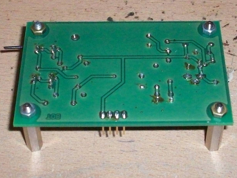
PCB for the BTM-222 and 5V level converters
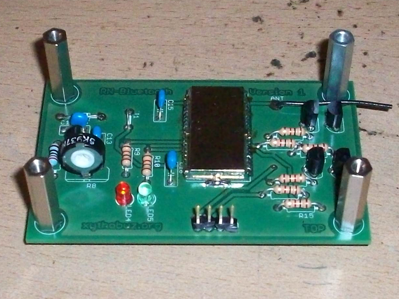
Here's the Layout of a BTM-222 Bluetooth PCB, following the Roboternetz Guidelines Mini Format. The circuit comes from Robotfreak, but is basically the minimal circuit described in the datasheet (370kB) (361 KiB).
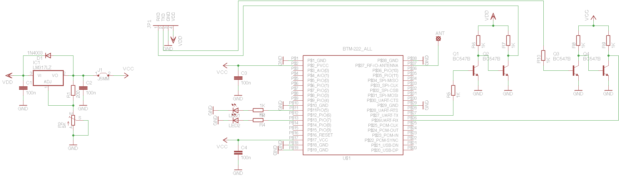

Layout and Circuit Diagram as Eagle files (54kB) (52 KiB).
| ID | Value | Shop |
|---|---|---|
| R1 | 200k Ohm | - |
| R2 | 5k Ohm Poti | Conrad |
| R3 - R10 | 1k Ohm | - |
| Q1 - Q4 | BC547 NPN | Conrad |
| IC1 | LM317(LZ) | Conrad |
| IC2 | BTM 222 | Ulrich Radig |
| LED 1+2 | LED 5mm | - |
Soldering the standard parts should be no problem. You should use a find soldering iron to connect each pin of the BTM-222, one after another. A 31mm long piece of wire can be used as antenna.
Interfacing the BTM-222
Before using the BTM-222 you have to configure it. You can change the speed, data format, name, PIN and some other things. You have to connect the hardware serial interface of the BTM-222 to a PC and issue the AT-Commands documented in the datasheet. It is very important to use only '\r' as Line-End-Character. Using '\n' or "\r\n" will result in error messages from the module.

