LARS v2
Upgrading the Looping Automated Rhythm Station
Project published on September 07, 2024.Last updated on September 16, 2024.
Recent activity in the repo: 
So you may have read about our project LARS. As mentioned I didn't have any hardware in the end to finish firmware development. So I slightly updated the circuitry, layed out a new board, had it manufactured in China and assembled at home.
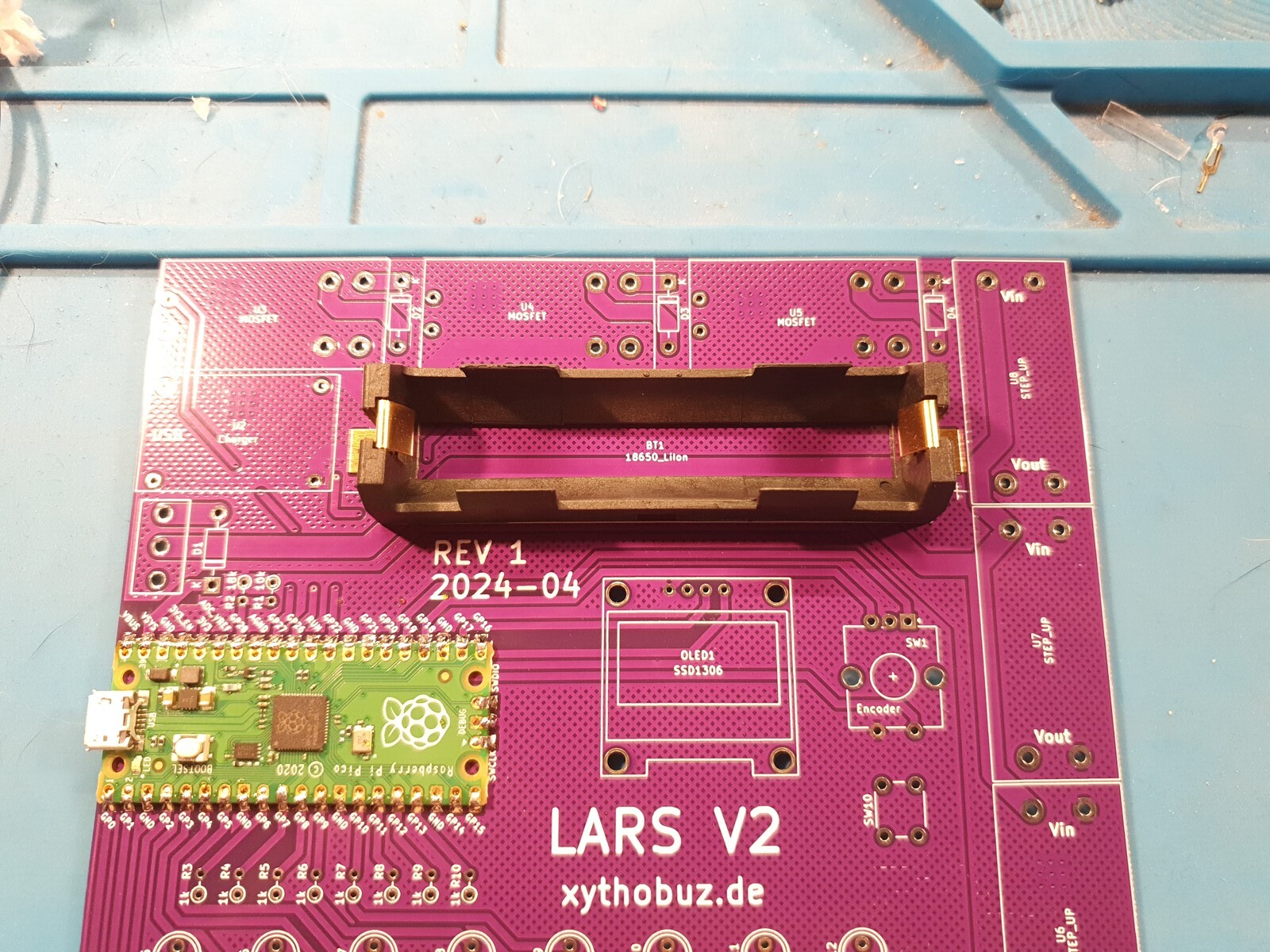
This is LARS v2, the second iteration of the same idea.
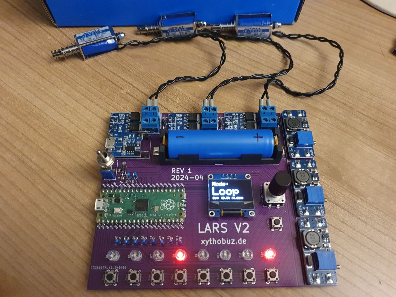

It's basically the same device, just with five additional switches. This allows for some more freedom in the user interface design. Now the loop mode can mute individual tracks. There's also USB MIDI support.

As usual I've added auto-generated documentation, including interactive 3D renders of the PCB and some usage hints. The gerber files and BOM to order your own are also available.
Unfortunately I'm kind of in the same situation now as with LARS v1. I've gone much further with the firmware, it's now mostly usable. But I've also given the hardware away again, so I can't finish it.
I should assemble another one soon...
Assembly Guide
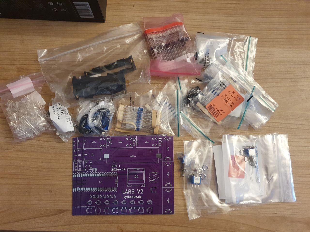
You want to build your own LARS v2 and have all the parts ready to go? Then let's build it!
In general you want to go from SMD / SMT (surface mount) parts to THT (through-hole), going from large to small for the SMD parts, and small to large for the THT parts.
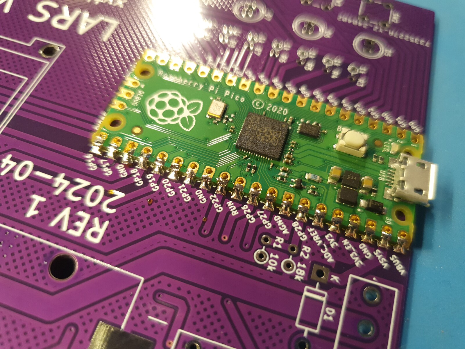
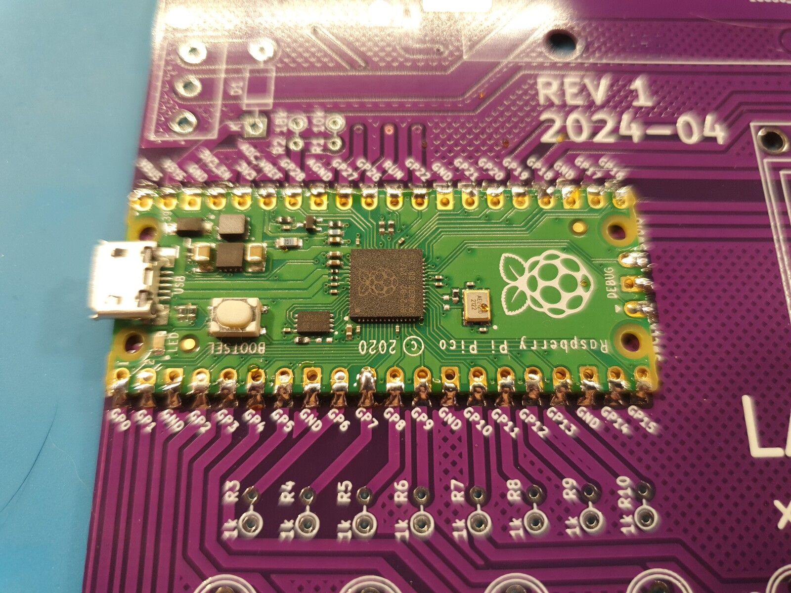
First place the SMD Raspberry Pi Pico module so all pads are properly aligned.


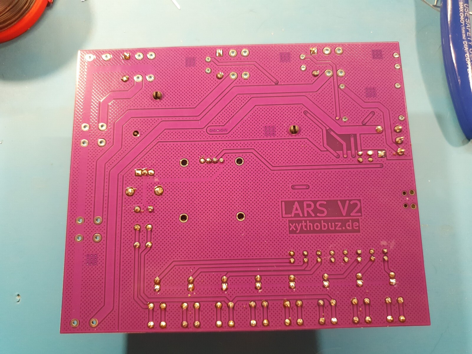
Now first solder on one corner, then go through both rows.

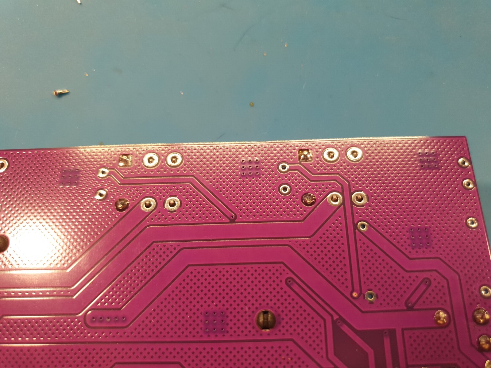
The battery holder snaps in with two plastic clips. Soldering the pads can be a bit tricky. Even though there is a hole for the solder to flow through to the pad, you can not see it well. Try to apply a bit of pressure to get the pads to connect reliably.

Now place all the pushbuttons and solder them in. Their legs have a snap fit so they will hold on properly.


Next the resistors. I'm bending their legs slightly so they stay in place when turning the board over.


The diodes and LEDs can be placed next, with the same leg-bending trick as before.


The encoder snaps in as well. For the switch and OLED, make sure to apply a bit of pressure when turning the board over, so they are firmly in place.

The pins of the MOSFET module screw-terminals fit into the board holes and can be soldered on directly. For the small logic pins use a bit of the cut-off legs from the LEDs or resistors.


For the regulator I'm using standard pins like they probably came with your Pico. But you could also use some more of the cut-off legs from the previous steps.


The charger pad does not quite fit the connections of the module. So I'm using two pins per connection in a 90 degree angle.


And that's it.

Good luck and have fun!

